Por qué una hidrolavadora sube y baja de presión
Separe oscilación del motor y pulsación hidráulica; después revise suministro, entrada, aire, boquilla, fugas, inyector, válvulas y descargador.
Primero describa qué oscila
Subir y bajar puede significar que el abanico cambia, la manguera golpea, el manómetro oscila, el motor acelera y desacelera o el descargador cicla con la pistola cerrada. Los síntomas se cruzan, pero no comparten una sola reparación. Registre cuándo ocurre y si cambia el sonido del motor.
No empiece girando el descargador. Las primeras revisiones suelen estar en el suministro y la boquilla, donde restricción, aire o desgaste alteran todo.
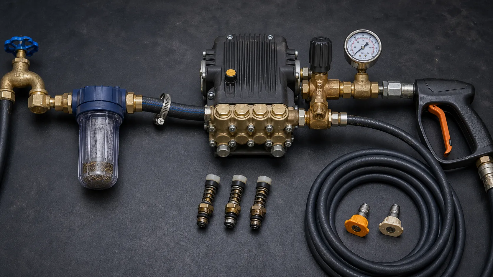
Pare antes de probar daño
Detenga ante manguera ampollada, conexión de alta presión con fuga, combustible, aceite bajo o contaminado, guarda rota, calor, vibración, ruido de molienda, cavitación persistente o pistola defectuosa. Aísle energía y libere presión.
Nunca tape una fuga con la mano. Una inyección a presión requiere atención médica urgente aunque parezca pequeña. No haga funcionar la bomba seca para comparar sonidos.
Separe motor inestable y pulsación hidráulica
Si varían las RPM, revise combustible, ventilación, filtro de aire, ahogador, gobernador, chispa, carga y mantenimiento según el manual. Una bomba que carga y descarga también mueve las RPM, por lo que observe manómetro y abanico al mismo tiempo.
Si el motor queda estable y pulsan agua y manómetro, enfoque suministro, aire, válvulas, boquilla, fugas, inyector y descargador. Las eléctricas pueden ciclar por diseño o por una fuga; siga su secuencia.
Verifique suministro bajo demanda
Una manguera llena con la máquina apagada puede no alimentar el caudal de trabajo. Confirme fuente, dispositivo antirretorno, diámetro, longitud, carrete, conexiones, tanque y línea de entrada según especificación. Abra por completo, quite dobleces y revise filtros.
Mida entrega con un método seguro y recipiente adecuado, y compárela con el requisito de entrada. La presión estática de la tubería no demuestra caudal útil. No conecte una fuente incapaz de alimentar continuamente.
Busque restricción y aire antes de la bomba
Filtro tapado, manguera colapsada, conexión pequeña, succión larga, elevación desde tanque, válvula cerrada o suciedad pueden privar la entrada. Abrazadera floja, manguera agrietada, O-ring, toma química vacía o conexión mal sellada introducen aire. Una fuga de succión puede aspirar sin gotear.
- Apague máquina y agua, y libere presión.
- Limpie el filtro según el manual.
- Revise interior de manguera, juntas, abrazaderas y conexiones.
- Simplifique la entrada a la configuración básica aprobada.
- Purgue aire antes de arrancar.
Un ruido como grava puede concordar con cavitación, pero no la prueba. Pare y corrija la entrada.
Confirme la boquilla, no solo el color
La presión depende de caudal y orificio. Un orificio gastado o grande reduce presión. Uno obstruido o pequeño aumenta carga e interacción con el descargador. El color suele indicar ángulo, no tamaño exacto.
Lea el tamaño estampado, consulte la tabla e inspeccione desgaste. Limpie solo como indica el fabricante; no agrande con broca o alambre. Pruebe una boquilla correcta antes de ajustar.
Use el estado del gatillo
| Cuándo ocurre | Qué priorizar |
|---|---|
| Solo al rociar | Caudal, aire, filtro, boquilla, válvulas, velocidad |
| Solo con gatillo cerrado | Pistola, manguera, conexión, inyector, fuga atrapada, ciclo del descargador |
| Al abrir | Transición normal o pico excesivo, boquilla, restricción |
| Después de minutos | Calor de bypass, fuente, tanque, alivio térmico, ventilación de combustible |
| Solo con toma química | Orientación, orificio, válvula, fuga, boquilla baja, viscosidad |
General Pump indica que un descargador que atrapa presión puede ciclar si la presión de la manguera se pierde. La fuga puede estar después aunque la pieza que se mueva sea el descargador.
Revise toda la ruta de alta presión
Inspeccione salida, descargador, alivios, inyector, acoples, manguera, giro del carrete, pistola, lanza y asiento de boquilla. Una fuga pequeña altera el comportamiento y es peligrosa. Reemplace dentro de capacidad; no repare roscas dañadas con más fuerza o sellador.
Sin presión, compruebe la válvula del inyector. Un inyector fuera del rango, manguera de descarga muy larga o restricción posterior también cambia la operación.
Válvulas y sellos vienen después
Con suministro, aire, boquilla, fugas y descargador verificados, válvulas de bomba gastadas, sucias o pegadas pueden pulsar. Los sellos dañados causan fuga, contaminación de aceite o pérdida. El servicio exige procedimiento, limpieza, torque y kit correctos.
No abra la bomba en un sitio sucio solo para mirar. Registre modelo, RPM, entrada, caudal, presión, aceite, temperatura y frecuencia para el técnico.
El descargador se ajusta al final
La configuración calificada usa boquilla, manómetro, suministro estable y secuencia del fabricante. No apriete para compensar desgaste o poca agua. Puede crear picos y sobrecarga.
Después de reparar, repita la prueba y observe transiciones. Deje enfriar y revise fugas. Un sistema de lavado a presión debe entregar caudal estable sin esconder un problema tras el ajuste.