Válvula descargadora, calor de bypass y alivio térmico
Siga el agua con gatillo abierto y cerrado, diferencie descarga, alivio de seguridad y alivio térmico, evite recirculación caliente y diagnostique ciclos sin ajustar a ciegas.
Una bomba en marcha debe mover agua
Una bomba común de hidrolavadora es de desplazamiento positivo. A velocidad de trabajo sigue entregando caudal. Cuando cierra la pistola, ese flujo no puede detenerse dentro. La válvula descargadora lo desvía al bypass mientras la salida de alta presión queda cerrada.
El cambio es rápido, pero no constituye un ralentí inocuo. Energía del motor, pérdidas mecánicas, fricción y recirculación calientan un volumen pequeño. El manual fija cuánto tiempo puede permanecer cerrado el gatillo.
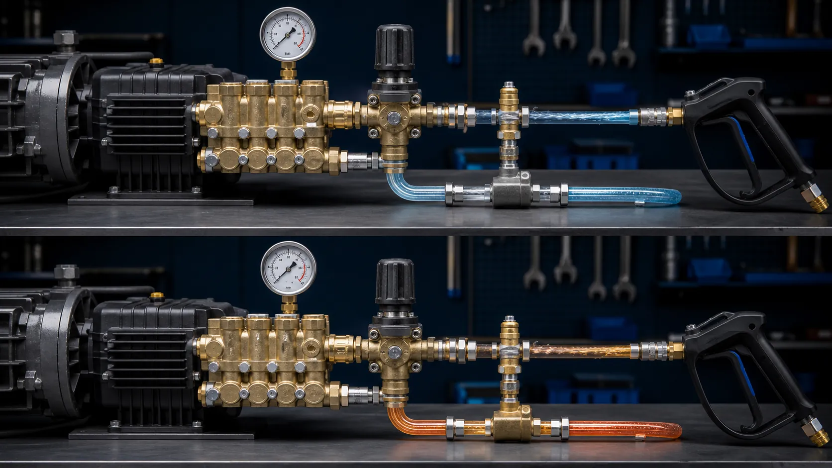
Estado con gatillo abierto
Con suministro suficiente, la bomba envía la mayor parte del caudal por descargador, manguera, pistola, lanza y boquilla correcta. La restricción del orificio crea presión para ese caudal. La ubicación del manómetro y el diseño influyen en la lectura.
Un sistema bien configurado puede mantener un pequeño flujo de bypass al rociar. General Pump lo describe como forma de limitar el pico y compensar parte del desgaste de boquilla. Es un detalle de configuración, no un porcentaje universal para todas las máquinas.
Estado con gatillo cerrado
Al cerrar, cambian presión y caudal. El descargador abre el bypass y aparta el flujo de la salida cerrada. Algunas máquinas compactas retornan a la entrada mediante un lazo corto. Otras regresan a un tanque, con mayor volumen y otro comportamiento térmico.
La manguera puede quedar presurizada, sobre todo con un descargador que atrapa presión. Considérela energía almacenada. Apague y accione la pistola en dirección segura antes de desconectar manguera, boquilla, inyector o unión.
Dos descargadores con respuesta distinta
| Comportamiento | Accionado por presión | Accionado por caudal |
|---|---|---|
| Inicio de descarga | Condición de presión | Cambio de flujo y comportamiento de presión |
| Al abrir gatillo | Respuesta a menudo inmediata | Puede subir presión gradualmente |
| Con pistola cerrada | Puede retener alta presión en la manguera | Depende del diseño e instalación |
| Sensibilidad | Exige boquilla, tubería y ajuste correctos | Las restricciones posteriores pueden alterarlo |
La tabla no sirve para sustituir piezas. Tipo, ubicación, retorno, acumulador, inyector, manguera, pistola y bomba forman un solo sistema. Use la documentación exacta.
Por qué se calienta un lazo corto
En un retorno a la entrada, la misma carga pequeña atraviesa la bomba repetidamente. Las pérdidas se convierten en calor y entra poca agua fría. Cabezal, sellos, válvulas, mangueras y admisión reciben mayor temperatura.
No espere vapor, olor o descarga. Si la pausa supera el límite del manual, apague. Abrir el gatillo cada pocos segundos no cuida el equipo: suma transiciones de presión y conserva intervalos de recirculación.
El alivio térmico es protección final
La válvula térmica detecta temperatura en su punto de montaje y abre al umbral diseñado para expulsar agua caliente y permitir entrada fría. Temperatura, flujo, rosca y reemplazo pertenecen a las especificaciones del componente.
Si descarga, pare y determine por qué se calentó. Puede haber protegido tras demasiado bypass, pero una fuga repetida también señala suciedad, asiento dañado o instalación incorrecta. Nunca tape la salida ni sustituya por una conexión no verificada.
Alivio de presión y térmico tienen trabajos distintos
El alivio de presión abre por sobrepresión. El térmico responde al calor. El descargador controla la transición normal entre trabajo y retorno. Uno no elimina a los otros cuando el diseño los exige.
General Pump recomienda un dispositivo secundario de seguridad además del descargador en sistemas de alta presión. Ajuste, descarga y capacidades deben seguir un diseño competente. Una válvula de seguridad no regula la presión diaria.
Configure con la boquilla correcta
La presión nace al forzar caudal por un orificio. Una boquilla gastada o grande reduce restricción. Una pequeña aumenta carga y puede acercar el sistema a sus límites. Seleccione por caudal real y presión prevista dentro de todas las capacidades.
Un técnico calificado debe ajustar el descargador con boquilla correcta, manómetro adecuado, suministro estable y procedimiento del fabricante. Una vez configurado, no es la perilla cotidiana para variar la fuerza. Cambie herramienta, boquilla, distancia, química o método sin sacar la máquina de su diseño.
El ciclo es un síntoma
Un descargador de presión puede alternar cuando se pierde la presión que debía quedar atrapada. La fuga puede estar en pistola, manguera, conexión, válvula del inyector o interior. También influyen falta de agua, aire, filtro bloqueado, boquilla incorrecta o desgaste.
- Pare y libere presión.
- Verifique suministro y filtro de entrada.
- Confirme boquilla y desgaste u obstrucción.
- Revise manguera, pistola, uniones, inyector y bypass.
- Compruebe aceite, temperatura, sonido y capacidades.
- Siga la secuencia del fabricante antes de ajustar.
Apretar el resorte para ocultar ciclos puede elevar picos o esconder una fuga. No desarme una válvula presurizada.
Condiciones para detenerse
- El alivio térmico descarga repetidamente o llega agua caliente a la entrada.
- El manómetro supera la capacidad del sistema.
- El descargador cicla con pistola cerrada o no libera como debe.
- La bomba hace ruido, vibra, pierde aceite o muestra calor anormal.
- La manguera se ampolla, una unión pierde, el gatillo falla o la descarga está tapada.
Apague energía, agua y combustible según el manual, libere presión y deje enfriar. Un sistema de lavado a presión controlado cambia de trabajo a bypass sin usar la seguridad como control normal.