From engine to surface: PSI, GPM, nozzles, and distance
How drive power, pump flow, nozzle restriction, fan angle, hose losses, and working distance combine to produce the stream that reaches a surface.
The machine rating is not the force at the wall
A pressure washer does not send its advertised PSI unchanged through every hose, nozzle, distance, and spray angle. The engine or motor turns a pump. The pump supplies flow. A correctly sized nozzle restricts that flow and creates working pressure. The hose, fittings, gun, lance, nozzle geometry, distance, and angle then shape what reaches the surface.
Understanding that chain prevents two common errors: treating maximum PSI as the only measure of cleaning ability and using a smaller nozzle to compensate for poor performance. The first ignores flow and spray geometry. The second can overload the pump, unloader, engine, hose, gun, fittings, or accessory.
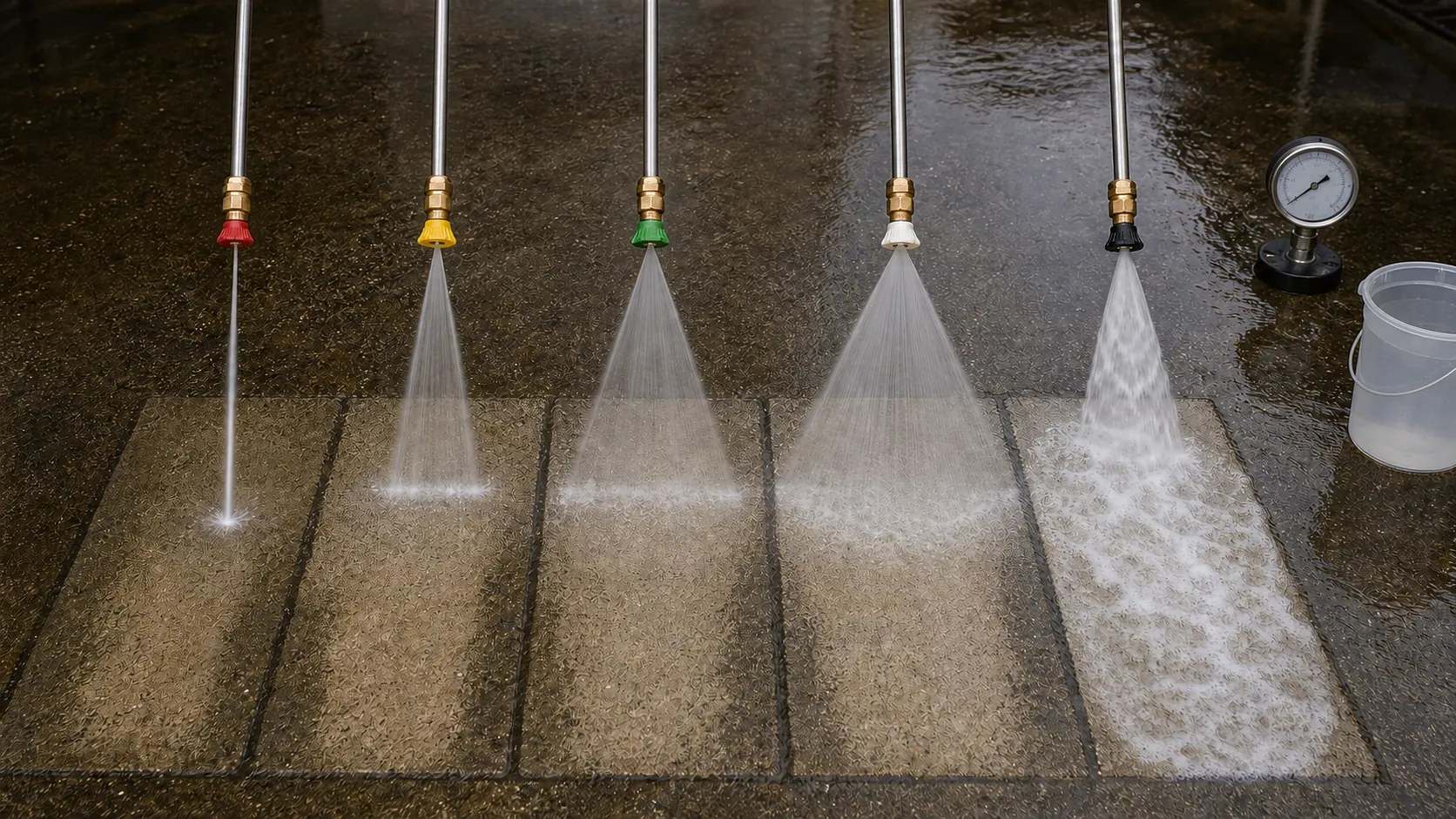
Follow the energy path
- Engine or electric motor: supplies rotational power within a rated speed and load range.
- Pump: turns inlet water into a nearly fixed displacement flow for a given speed and pump design.
- Unloader or regulator: directs flow toward the spray circuit when the gun is open and into bypass when the gun closes, according to the system design.
- High-pressure hose and fittings: contain the working pressure while adding friction and localized restrictions.
- Gun and lance: give the operator a rated shutoff and a way to position the nozzle.
- Nozzle: creates the final restriction and forms the stream or fan.
- Surface: receives a result modified by distance, angle, movement, material condition, soil, temperature, and chemistry.
Every pressure-side component must be rated for the actual system. The allowable working pressure is governed by the lowest-rated pump, unloader, hose, gun, fitting, lance, nozzle holder, surface cleaner, injector, or other accessory in the path.
PSI describes pressure, not the whole cleaning process
PSI is pounds per square inch. On a pressure washer, it describes pressure in the system under stated conditions. It does not by itself state how much water reaches the surface or how that water is distributed.
A narrow stream concentrates available flow into a small impact area. A broad fan distributes it over a wider path. Moving closer makes either pattern smaller and more concentrated. Those changes can be useful, but they can also cut soft material, etch concrete, remove oxidation unevenly, drive water through joints, or cause injection injuries.
Rated maximum pressure, measured pressure at the pump, pressure near the gun, and effective impact at the surface are different ideas. A suitable pressure gauge installed in the location and manner specified by the equipment manufacturer is more useful for setup than guessing from sound or recoil.
GPM moves contamination and covers area
GPM is gallons per minute. Higher usable flow can wet a larger area, feed a wider fan, carry loosened material, and rinse soil and chemistry more effectively. Flow is one reason a lower-pressure commercial machine can complete a compatible cleaning task more efficiently than a higher-PSI unit with limited water volume.
The inlet must support the required flow. A restricted faucet, small or long supply hose, clogged inlet screen, air leak, warm inlet water, collapsed hose, or inadequate tank feed can starve the pump. Cavitation and poor inlet conditions damage equipment and make downstream troubleshooting misleading.
Measure the source under realistic conditions before the job. Confirm hose diameter, length, elevation change, tank level, and any other users on the supply. A pump cannot deliver its rated flow for long if the inlet cannot replace that water.
PSI multiplied by GPM is only a rough comparison
Multiplying PSI by GPM produces a simple cleaning-unit number that can compare broad machine ratings. It does not include nozzle angle, distance, duty cycle, temperature, chemical action, surface response, hose losses, or operator technique. Two systems with the same product can behave differently at the surface.
Hydraulic power also has a limit. The ideal water horsepower is approximately PSI multiplied by GPM and divided by 1,714. The drive must supply more than that ideal result because pumps and drives are not perfectly efficient. Pairing a high-flow pump with an undersized engine does not create free pressure; speed can drop, the engine can overload, and the system will miss its rated point.
Nozzle orifice size sets the operating point
Pressure-washer nozzles are identified by spray angle and an orifice-size designation. The size number is a flow reference, not a direct inch measurement. Select it from the pump or nozzle manufacturer's chart using the machine's actual flow and intended pressure.
An orifice that is too small restricts the flow enough to drive pressure above the intended setting or force the unloader to divert excess flow. That can overload components and create heat in bypass. An orifice that is too large lowers working pressure and may produce a weak or poorly formed spray.
Nozzles wear. Abrasive water and normal use enlarge the orifice, so pressure can gradually fall even though the engine and pump sound normal. Inspect, clean, and replace nozzles according to the manufacturer. Never use wire, drill bits, or an improvised object that changes the opening.
Fan angle changes concentration
| Pattern | Practical behavior | Main caution |
|---|---|---|
| Zero-degree stream | Concentrates flow in a very small area and reaches farther | Severe injury and surface-damage potential; rarely suitable for general cleaning |
| Narrow fan | Provides concentrated impact with a visible working width | Can leave cut marks, stripes, or etched areas when held close or moved unevenly |
| Medium fan | Balances coverage and controlled impact for many compatible tasks | Still requires a test, stable distance, overlap, and material awareness |
| Wide fan or low-pressure pattern | Spreads flow for rinsing, chemical application, or sensitive work depending on the nozzle system | Color and appearance do not prove pressure or chemical compatibility |
Industry color conventions are common, but the stamped angle and orifice, manufacturer chart, and measured operating pressure are the reliable references. A faded or replacement nozzle may not follow the color expected by the operator.
Distance and angle finish the setup
As the nozzle moves away, the fan widens and the impact concentration falls. The pattern also becomes more vulnerable to wind. Moving closer narrows the working band and raises the risk of visible overlap errors. Establish distance on a representative test area, then maintain it through body position or a controlled lance angle.
A stream directed squarely at a joint can force water inward. A shallow angle can help carry loose contamination along a durable surface, but it may also drive debris beneath a lap or across unprotected property. The correct angle follows the assembly, drainage path, and target soil.
Keep the nozzle moving before entering a visible area and continue the movement past the end of the pass. Starting or stopping while aimed at one point concentrates the stream and commonly leaves wand marks.
Where pressure disappears
Some pressure loss through hose and fittings is normal. Longer hose, smaller internal diameter, higher flow, restrictive swivels, undersized quick connects, filters in the wrong circuit, and elevation can increase losses. A surface cleaner, injector, telescoping lance, or hose reel adds its own requirements.
Do not diagnose every pressure complaint by adjusting the unloader. First confirm water supply, engine speed, pump flow, nozzle size and wear, leaks, trapped air, filter condition, hose and accessory ratings, and whether the chemical injector is operating in the intended pressure range. Set or service the unloader only by the manufacturer's procedure and with appropriate measurement.
A controlled field setup
- Read the pump and machine data plates and identify the lowest-rated pressure-side component.
- Confirm a clean, adequate inlet supply and purge air with the machine off as directed.
- Choose a nozzle from the manufacturer's flow and pressure chart, then inspect its angle and orifice marking.
- Route and inspect hoses, fittings, gun, lance, and accessories before pressurizing.
- Start and warm the equipment according to its manual, with the gun controlled and the nozzle pointed into a safe area.
- Verify working pressure with the correct gauge and confirm that the unloader returns the system to normal operation.
- Test the surface from a conservative distance using a broad compatible pattern.
- Adjust one variable at a time and inspect the dry result before treating the full area.
The surface sets the final limit
A system can be mechanically capable of a pressure that the substrate cannot tolerate. Concrete age, brick hardness, mortar condition, wood grain, oxidation, coating adhesion, sealant, window joints, electrical penetrations, and prior repairs all impose limits below the machine rating.
A professional power-washing plan therefore records both sides of the equation: what the equipment delivers and what the surface accepts. The nozzle is not a cure for a process that ignores one of them.